Need Help?
Saudi Arabia +966-594098404, +966-536598520
Pakistan +92-3074690091

DILET 70-A – Analogue Timer
SKU: DILET70-A
Specifications
CATEGORY:
PRODUCT BRAND:
PRODUCT NAME:
DILET 70-A – Analogue Timer
PRODUCT NUMBER:
DILET70-A
AVAILABILITY:
On-Demand
DESCRIPTION
Delivery programme
Product range | DILET timing relays | ||
Basic function | Timer relays | ||
Function | Multi-functional On-delayed Off-delayed Fleeting contact on energization Fleeting contact on de-energization Flashing, pulse initiating On- and Off-delayed Pulse forming Pulse generating | ||
| with connection for potentiometer Adjustable timing functions | |||
Number of changeover contacts | 1 | ||
Time range | 0.05 s – 60 h | ||
Time range |
0.15 – 3 s 0.5 – 10 s 3 – 60 s 0,15 – 3 min 0.5 – 10 min 3 – 60 min 0.15 – 3 h 0.5 – 10 h 3 – 60 h | ||
Rated operational current | |||
AC-11 | |||
230 V | Ie | A | 3 |
380 V 400 V 415 V | Ie | A | 3 |
AC-15 | |||
220 V 230 V 240 V | Ie | A | 3 |
Voltage range | ULN | V | 24 – 240 V AC, 50/60 Hz 24 – 240 V DC |
Width | mm | 45 | |
| Terminal marking according to EN 50042 | |||
| General | |||
Standards | Standard IEC/EN 61812 VDE 0435 | ||
Lifespan, mechanical | |||
AC operated | Operations | x 106 | 30 |
DC operated | Operations | x 106 | 30 |
Climatic proofing | Damp heat, constant, to IEC 60068-2-78 Damp heat, cyclic, to IEC 60068-2-30 | ||
Ambient temperature | |||
Open | °C | -20 – +60 | |
Enclosed | °C | – 20 – + 45 | |
Mounting position | As required | ||
Mechanical shock resistance (IEC/EN 60068-2-27) | |||
Half-sinusoidal shock, 20 ms | g | ||
Make contact | g | 4 | |
Degree of protection | |||
Terminals | IP20 | ||
Weight | kg | 0.09 | |
Terminal capacities | mm2 | ||
Solid | mm2 | 1 x (0.75 – 2.5) 2 x (0.75 – 2.5) | |
Flexible with ferrule | mm2 | 1 x (0.75 – 1.5) 2 x (0.75 – 1.5) | |
Solid or stranded | AWG | 1 x (18 – 14) | |
| Contacts | |||
Rated impulse withstand voltage | Uimp | V AC | 6000 |
Overvoltage category/pollution degree | III/2 | ||
Rated insulation voltage | Ui | V AC | 600 |
Rated operational voltage | Ue | V AC | 440 |
Safe isolation to EN 61140 | |||
between coil and auxiliary contacts | V AC | 250 | |
between the auxiliary contacts | V AC | 250 | |
Making capacity | |||
AC-14 cos ϕ = 0.3400 V | A | 48 | |
AC-15 cos ϕ = 0.3 220 V | A | 50 | |
DC-11 L/R – 40 ms | x Ie | 1.1 | |
Breaking capacity | |||
AC-14 cos ϕ = 0.3440 V | A | 3 | |
AC-15 cos ϕ = 0.3220 V | A | 3 | |
DC-11 L/R – 40 ms | x Ie | 1.1 | |
Rated operational current | Ie | A | |
AC–14 | |||
440 V | Ie | A | 3 |
AC-15 | |||
220 V 230 V 240 V | Ie | A | 3 |
DC-11 | |||
Note | Making and breaking conditions to DC13, time constant as stated | ||
L/R max. 15 ms | A | ||
24 V | Ie | A | 1.5 |
L/R max. 50 ms | A | 1.2 | |
Conv. thermal current | Ith | A | 6 |
Short-circuit rating without welding | |||
Note | When supplied directly from mains or transformer > 1000 VA | ||
Max. fuse, make contacts | A gG/gL | 6 | |
Max. fuse, break contacts | A gG/gL | 6 | |
| Magnet systems | |||
Rated operational voltage | Ue | V | |
AC | 24 – 240 | ||
DC | 24 – 240 | ||
Voltage tolerance | x Uc | ||
Pick-up voltage | x Us | ||
Min. pick-up voltage, AC operated | x Uc | 0.85 | |
Pick-up voltage AC operated, max. | x Uc | 1.1 | |
Pick-up voltage DC operated, min. | x Uc | 0.7 | |
Max. pick-up voltage, DC operated | x Uc | 1.1 | |
Power consumption | |||
Pick-up AC | VA | 2 | |
Sealing AC | VA | 2 | |
Pick-up DC | W | 1.8 | |
Sealing DC | W | 1.8 | |
Duty factor | % DF | 100 | |
Maximum operating frequency | Ops/h | 4000 | |
Minimum command time | |||
AC | ms | 50 | |
DC | ms | 30 | |
Repetition accuracy (deviation) | % | ||
Technical data for design verification | |||
Rated operational current for specified heat dissipation | In | A | 6 |
Heat dissipation per pole, current-dependent | Pvid | W | 0.9 |
Equipment heat dissipation, current-dependent | Pvid | W | 0 |
Static heat dissipation, non-current-dependent | Pvs | W | 1.8 |
Heat dissipation capacity | Pdiss | W | 0 |
Operating ambient temperature min. | °C | -20 | |
Operating ambient temperature max. | °C | 60 | |
IEC/EN 61439 design verification | |||
10.2 Strength of materials and parts | |||
10.2.2 Corrosion resistance | Meets the product standard’s requirements. | ||
10.2.3.1 Verification of thermal stability of enclosures | Meets the product standard’s requirements. | ||
10.2.3.2 Verification of resistance of insulating materials to normal heat | Meets the product standard’s requirements. | ||
10.2.3.3 Verification of resistance of insulating materials to abnormal heat and fire due to internal electric effects | Meets the product standard’s requirements. | ||
10.2.4 Resistance to ultra-violet (UV) radiation | Meets the product standard’s requirements. | ||
10.2.5 Lifting | Does not apply, since the entire switchgear needs to be evaluated. | ||
10.2.6 Mechanical impact | Does not apply, since the entire switchgear needs to be evaluated. | ||
10.2.7 Inscriptions | Meets the product standard’s requirements. | ||
10.3 Degree of protection of ASSEMBLIES | Does not apply, since the entire switchgear needs to be evaluated. | ||
10.4 Clearances and creepage distances | Meets the product standard’s requirements. | ||
10.5 Protection against electric shock | Does not apply, since the entire switchgear needs to be evaluated. | ||
10.6 Incorporation of switching devices and components | Does not apply, since the entire switchgear needs to be evaluated. | ||
10.7 Internal electrical circuits and connections | Is the panel builder’s responsibility. | ||
10.8 Connections for external conductors | Is the panel builder’s responsibility. | ||
10.9 Insulation properties | |||
10.9.2 Power-frequency electric strength | Is the panel builder’s responsibility. | ||
10.9.3 Impulse withstand voltage | Is the panel builder’s responsibility. | ||
10.9.4 Testing of enclosures made of insulating material | Is the panel builder’s responsibility. | ||
10.10 Temperature rise | The panel builder is responsible for the temperature rise calculation. Eaton will provide heat dissipation data for the devices. | ||
10.11 Short-circuit rating | Is the panel builder’s responsibility. The specifications for the switchgear must be observed. | ||
10.12 Electromagnetic compatibility | Is the panel builder’s responsibility. The specifications for the switchgear must be observed. | ||
10.13 Mechanical function | The device meets the requirements, provided the information in the instruction leaflet (IL) is observed. | ||
Item reviews
Only logged in customers who have purchased this product may leave a review.
Related products
-

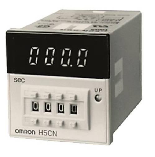
48 x 48 x 83.4 mm, 100 to 240 VAC, Time range 1 s to 5999 s (1 range), Output SPDT, 11-pin round socket
Read more -

Omron Automation and Safety H5S-WB2
Read more -

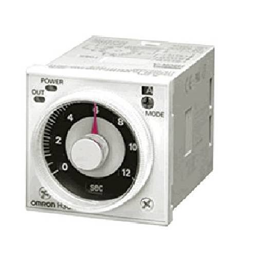
OMRON H3CR-A8E AC100-240V/DC100-125V 50/60HZ Solid-state Multi-functional Timer (8-pin) NN
Read more -

Omron timer counter
Read more -

Multiple Operating Modes and Multiple Time Ranges. DIN 48 x 48-mm Multifunctional Timer.
$1.00 Add to cart


Reviews
There are no reviews yet.