Need Help?
Saudi Arabia +966-594098404, +966-536598520
Pakistan +92-3074690091

The New E5CC, E5CC-U, E5EC, E5AC, and E5DC Next-generation Digital Controllers with Advanced Designs and Easy Operation
White PV display and new LCD with greatly improved visibility.*
* 100 times higher contrast ratio than the E5Z.
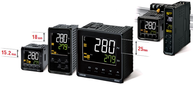
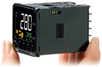
A compact body with large display characters for easy reading even from a distance.
This helps to reduce human error.
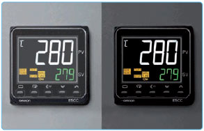
The white LCD display is easy to read in the subdued lighting conditions.
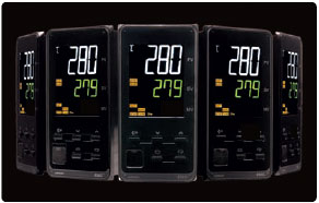
The display remains easy to read even from wide viewing angles.
Save space!
The compact and space-saving design of the new E5CC/E5EC/E5AC controller generation requires less space behind the panel (60 mm), allowing quick snap-mounting and easy installation even under very cramped conditions.*
* Excluding E5CC-U and E5DC
Save Time!
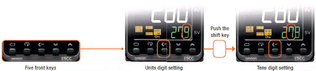
The E5CC/E5CC-U/E5EC/E5AC/E5DC series is extremely easy to operate using the instrument’s five front keys.
Smart!
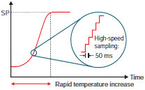
With key features like simplicity in operation, Omron’s patented PID control, and 50ms sampling period, the E5CC/E5CC-U/E5EC/E5AC/E5DC sets a new standard in fast and precise temperature regulation.
Sampling period:50ms
Sampling Rate Sufficient to Handle Rapid Increases in Temperature
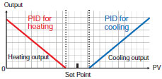
Independent heating/cooling PID
The heating and cooling PID can each be set individually. Also, autotuning (AT) will automatically set the PID constants.
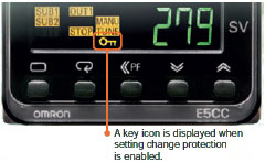
Setting change protection
You can disable key operations to help prevent incorrect setting change.
Easy connections to a PLC with programless communications.
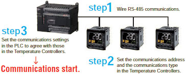
Advantages
・ The amount of work to set up the system is greatly reduced.
・ PLC programming and memory are not required for communications.
・ Communications even with multiple Temperature Controllers are automatically executed by the Temperature Controllers.
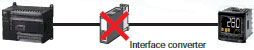
・ Interface converters are not required, which reduces costs.
・ Number of connected Digital Temperature Controllers: 32 max. (Up to 16 for the FX Series)
・ PLC programming and memory are not required for communications.
・ Communications even with multiple Temperature Controllers are automatically executed by the Temperature Controllers.
・ Interface converters are not required, which reduces costs.
・ Number of connected Digital Temperature Controllers: 32 max. (Up to 16 for the FX Series)
More Convenient Operations
The parameters can be copied from the master Temperature Controller to slave Temperature Controllers.
Master Temperature Controller can share RUN/STOP operations and set points with slave Temperature Controllers.
Slope and offsets can be set for the set point.
Note: A Temperature Controller with version 1.1 or higher is required.
A Temperature Controller with version 2.1 or higher is required for the FX Series.
| Power supply voltage | A in model number: 100 to 240 VAC, 50/60 Hz D in model number: 24 VAC, 50/60 Hz; 24 VDC | |
|---|---|---|
| Operating voltage range | 85% to 110% of rated supply voltage | |
| Power consumption | Models with option selection of 000:5.2 VA max. at 100 to 240 VAC, and 3.1 VA max. at 24 VAC or 1.6 W max. at 24 VDC All other models: 6.5 VA max. at 100 to 240 VAC, and 4.1 VA max. at 24 VAC or 2.3 W max. at 24 VDC | |
| Sensor input | Temperature input Thermocouple: K, J, T, E, L, U, N, R, S, B, C/W, or PL II Platinum resistance thermometer: Pt100 or JPt100 Infrared temperature sensor (ES1B): 10 to 70°C, 60 to 120°C, 115 to 165°C, or 140 to 260°C Analog input Current input: 4 to 20 mA or 0 to 20 mA Voltage input: 1 to 5 V, 0 to 5 V, or 0 to 10 V | |
| Input impedance | Current input: 150 Ω max., Voltage input: 1 MΩ min. (Use a 1:1 connection when connecting the ES2-HB-N/THB-N.) | |
| Control method | ON/OFF control or 2-PID control (with auto-tuning) | |
| Control output | Relay output | E5CC-800: SPST-NO, 250 VAC, 3 A (resistive load), electrical life: 100,000 operations, minimum applicable load: 5 V, 10 mA E5CC-U-800: SPDT, 250 VAC, 3 A (resistive load), electrical life: 100,000 operations, minimum applicable load: 5 V, 10 mA |
| Voltage output (for driving SSR) | Output voltage: 12 VDC ± 20% (PNP), max. load current: 21 mA, with short-circuit protection circuit | |
| Linear current output | 4 to 20 mA DC/0 to 20 mA DC, load: 500 Ω max., resolution: approx. 10,000 | |
| Auxiliary output | Number of outputs | 2 |
| Output specifications | SPST-NO relay outputs, 250 VAC, Models with 2 outputs: 3 A (resistive load), Electrical life: 100,000 operations, Minimum applicable load: 10 mA at 5 V | |
| Event input | Number of inputs | 2 or 4 (depends on model) |
| External contact input specifications | Contact input: ON: 1 kΩ max., OFF: 100 kΩ min. | |
| Non-contact input: ON: Residual voltage: 1.5 V max., OFF: Leakage current: 0.1 mA max. | ||
| Current flow: Approx. 7 mA per contact | ||
| Setting method | Digital setting using front panel keys | |
| Indication method | 11-segment digital display and individual indicators Character height: PV: 15.2 mm, SV: 7.1 mm | |
| Multi SP | Up to eight set points (SP0 to SP7) can be saved and selected using event inputs, key operations, or serial communications. | |
| Other functions | Manual output, heating/cooling control, loop burnout alarm, SP ramp, other alarm functions, heater burnout (HB) alarm (including SSR failure (HS) alarm), 40% AT, 100% AT, MV limiter, input digital filter, self tuning, PV input shift, run/stop, protection functions, temperature status display, moving average of input value | |
| Ambient operating temperature | -10 to 55°C (with no condensation or icing), for 3-year warranty: -10 to 50°C (with no condensation or icing) | |
| Ambient operating humidity | 25% to 85% | |
| Storage temperature | -25 to 65°C (with no condensation or icing) | |
| Altitude | 2,000 m max. | |
| Recommended fuse | T2A, 250 VAC, time lag, low shut-off capacity | |
| Installation environment | Installation Category II, Pollution Class 2 (IEC 61010-1 compliant) | |
Note: There are no optional functions for the E5CC-U-800. Refer to Model Number Legend on Lineup.
Input Ranges (Universal inputs)
Thermocouple/Platinum Resistance Thermometer
Analog input
| Input type | Current | Voltage | |||
|---|---|---|---|---|---|
| Input specification | 4 to 20 mA | 0 to 20 mA | 1 to 5 V | 0 to 5 V | 0 to 10 V |
| Setting range | Usable in the following ranges by scaling: -1999 to 9999, -199.9 to 999.9, -19.99 to 99.99 or -1.999 to 9.999 | ||||
| Set value | 25 | 26 | 27 | 28 | 29 |
Alarm Outputs
Each alarm can be independently set to one of the following 19 alarm types. The default is 2: Upper limit. (see note.)
Auxiliary outputs are allocated for alarms. ON delays and OFF delays (0 to 999 s) can also be specified.
| Set value | Alarm type | Alarm output operation | Description of function | |
|---|---|---|---|---|
| When alarm value X is positive | When alarm value X is negative | |||
| 0 | Alarm function OFF | Output OFF | No alarm | |
| 1 | Upper- and lower-limit *1 |  | *2 | Set the upward deviation in the set point for the alarm upper limit (H) and the lower deviation in the set point for the alarm lower limit (L). The alarm is ON when the PV is outside this deviation range. |
| 2 (default) | Upper-limit |  |  | Set the upward deviation in the set point by setting the alarm value (X). The alarm is ON when the PV is higher than the SP by the deviation or more. |
| 3 | Lower-limit |  |  | Set the downward deviation in the set point by setting the alarm value (X). The alarm is ON when the PV is lower than the SP by the deviation or more. |
| 4 | Upper- and lower-limit range *1 |  | *3 | Set the upward deviation in the set point for the alarm upper limit (H) and the lower deviation in the set point for the alarm lower limit (L). The alarm is ON when the PV is inside this deviation range. |
| 5 | Upper- and lower-limit with standby sequence *1 | *5 | *4 | A standby sequence is added to the upper- and lower-limit alarm (1). *6 |
| 6 | Upper-limit with standby sequence | | | A standby sequence is added to the upper-limit alarm (2). *6 |
| 7 | Lower-limit with tandby sequence | | | A standby sequence is added to the lower-limit alarm (3). *6 |
| 8 | Absolute-value upper-limit |  |  | The alarm will turn ON if the process value is larger than the alarm value (X) regardless of the set point. |
| 9 | Absolute-value lower-limit |  |  | The alarm will turn ON if the process value is smaller than the alarm value (X) regardless of the set point. |
| 10 | Absolute-value upper-limit with standby sequence | | | A standby sequence is added to the absolute-value upper-limit alarm (8). *6 |
| 11 | Absolute-value lower-limit with standby sequence | | | A standby sequence is added to the absolute-value lower-limit alarm (9). *6 |
| 12 | LBA (alarm 1 type only) | – | *7 | |
| 13 | PV change rate alarm | – | *8 | |
| 14 | SP absolute value upper limit alarm |  |  | This alarm type turns ON the alarm when the set point (SP) is higher than the alarm value (X). |
| 15 | SP absolute value lower limit alarm |  |  | This alarm type turns ON the alarm when the set point (SP) is lower than the alarm value (X). |
| 16 | MV absolute value upper limit alarm *9 | Standard Control | Standard Control | This alarm type turns ON the alarm when the manipulated variable (MV) is higher than the alarm value (X). |
| Heating/Cooling Control (Heating MV) | Heating/Cooling Control (Heating MV) Always ON | |||
| 17 | MV absolute value lower limit alarm *9 | Standard Control | Standard Control | This alarm type turns ON the alarm when the manipulated variable (MV) is lower than the alarm value (X). |
| Heating/Cooling Control (Cooling MV) | Heating/Cooling Control (Cooling MV) Always ON | |||
*1 With set values 1, 4 and 5, the upper and lower limit values can be set independently for each alarm type, and are
expressed as “L” and “H.”
*2 Set value: 1, Upper- and lower-limit alarm

*3 Set value: 4, Upper- and lower-limit range
*4 Set value: 5, Upper- and lower-limit with standby sequence
For Upper- and Lower-Limit Alarm Described Above *2
• Case 1 and 2
Always OFF when the upper-limit and lower-limit hysteresis overlaps.
• Case 3: Always OFF
*5. Set value: 5, Upper- and lower-limit with standby sequence
Always OFF when the upper-limit and lower-limit hysteresis overlaps.
*6 Refer to the E5[]C Digital Controllers User’s Manual (Cat. No. H174) for information on the operation of the standby
sequence.
*7 Refer to the E5[]C Digital Controllers User’s Manual (Cat. No.H174) for information on the loop burnout alarm (LBA).
*8 Refer to the E5[]C Digital Controllers User’s Manual (Cat. No. H174) for information on the PV change rate alarm.
*9 When heating/cooling control is performed, the MV absolute upper limit alarm functions only for the heating operation
and the MV absolute lower limit alarm functions only for the cooling operation.
expressed as “L” and “H.”
*2 Set value: 1, Upper- and lower-limit alarm

*3 Set value: 4, Upper- and lower-limit range

*4 Set value: 5, Upper- and lower-limit with standby sequence
For Upper- and Lower-Limit Alarm Described Above *2
• Case 1 and 2
Always OFF when the upper-limit and lower-limit hysteresis overlaps.
• Case 3: Always OFF
*5. Set value: 5, Upper- and lower-limit with standby sequence
Always OFF when the upper-limit and lower-limit hysteresis overlaps.
*6 Refer to the E5[]C Digital Controllers User’s Manual (Cat. No. H174) for information on the operation of the standby
sequence.
*7 Refer to the E5[]C Digital Controllers User’s Manual (Cat. No.H174) for information on the loop burnout alarm (LBA).
*8 Refer to the E5[]C Digital Controllers User’s Manual (Cat. No. H174) for information on the PV change rate alarm.
*9 When heating/cooling control is performed, the MV absolute upper limit alarm functions only for the heating operation
and the MV absolute lower limit alarm functions only for the cooling operation.
Characteristics
| Indication accuracy (at the ambient temperature of 23°C) | E5CC-800 Thermocouple: (±0.3% of PV or ±1°C, whichever is greater) ±1 digit max. *1 Platinum resistance thermometer: (±0.2% of PV or ±0.8°C, whichever is greater) ±1 digit Analog input: ±0.2% FS ±1 digit max. CT input: ±5% FS ±1 digit max. E5CC-U-800 Thermocouple: (±1% of PV or ±2°C, whichever is greater) ±1 digit max. *1 Platinum resistance thermometer: (±0.2% of PV or ±0.8°C, whichever is greater) ±1 digit Analog input: ±0.2% FS ±1 digit max. | |
|---|---|---|
| Simple transfer output accuracy | ±0.3% FS max.*2 | |
| Influence of temperature *3 | Thermocouple input (R, S, B, C/W, PL II): (±1% of PV or ±10°C, whichever is greater) ±1 digit max. Other thermocouple input: (±1% of PV or ±4°C, whichever is greater) ±1 digit max. *4 Platinum resistance thermometer: (±1% of PV or ±2°C, whichever is greater) ±1 digit max. Analog input: ±1%FS ±1 digit max. CT input: ±5%FS ±1 digit max. | |
| Influence of voltage *3 | ||
| Influence of EMS. (at EN 61326-1) | ||
| Input sampling period | 50 ms | |
| Hysteresis | Temperature input: 0.1 to 999.9°C or °F (in units of 0.1°C or °F) Analog input: 0.01% to 99.99% FS (in units of 0.01% FS) | |
| Proportional band (P) | Temperature input: 0.1 to 999.9°C or °F (in units of 0.1°C or °F) Analog input: 0.1% to 999.9% FS (in units of 0.1% FS) | |
| Integral time (I) | 0 to 9999 s (in units of 1 s), 0.0 to 999.9 s (in units of 0.1 s) *5 | |
| Derivative time (D) | 0 to 9999 s (in units of 1 s), 0.0 to 999.9 s (in units of 0.1 s) *5 | |
| Proportional band (P) for cooling | Temperature input: 0.1 to 999.9°C or °F (in units of 0.1°C or °F) Analog input: 0.1% to 999.9% FS (in units of 0.1% FS) | |
| Integral time (I) for cooling | 0 to 9999 s (in units of 1 s), 0.0 to 999.9 s (in units of 0.1 s) *5 | |
| Derivative time (D) for cooling | 0 to 9999 s (in units of 1 s), 0.0 to 999.9 s (in units of 0.1 s) *5 | |
| Control period | 0.1, 0.2, 0.5, 1 to 99 s (in units of 1 s) | |
| Manual reset value | 0.0 to 100.0% (in units of 0.1%) | |
| Alarm setting range | -1999 to 9999 (decimal point position depends on input type) | |
| Affect of signal source resistance | Thermocouple: 0.1°C/Ω max. (100 Ωmax.) Platinum resistance thermometer: 0.1°C/Ω max. (10 Ω max.) | |
| Insulation resistance | 20 MΩ min. (at 500 VDC) | |
| Dielectric strength | 3,000 VAC, 50/60 Hz for 1 min between terminals of different charge | |
| Vibration | Malfunction | 10 to 55 Hz, 20 m/s2 for 10 min each in X, Y, and Z directions |
| Resistance | 10 to 55 Hz, 20 m/s2 for 2 hrs each in X, Y, and Z directions | |
| Shock | Malfunction | 100 m/s2, 3 times each in X, Y, and Z directions |
| Resistance | 300 m/s2, 3 times each in X, Y, and Z directions | |
| Weight | E5CC-800: Controller: Approx. 120 g, Mounting Bracket: Approx. 10 g E5CC-U-800: Controller: Approx. 100 g, Mounting Bracket: Approx. 10 g | |
| Degree of protection | E5CC-800: Front panel: IP66, Rear case: IP20, Terminals: IP00 E5CC-U-800: Front panel: IP50, Rear case: IP20, Terminals: IP00 | |
| Memory protection | Non-volatile memory (number of writes: 1,000,000 times) | |
| Standards | Approved standards | cULus: UL 61010-1/CSA C22.2 No.61010-1 *6, Korean wireless regulations (Radio law: KC Mark) (Some models only.) *7, Lloyd’s standards *8, EAC |
| Conformed standards | EN 61010-1 (IEC 61010-1), RCM | |
| EMC | EMI: EN 61326-1 *8 Radiated Interference Electromagnetic Field Strength: EN 55011 Group 1, class A Noise Terminal Voltage: EN 55011 Group 1, class A EMS: EN 61326-1 *8 ESD Immunity: EN 61000-4-2 Electromagnetic Field Immunity: EN 61000-4-3 Burst Noise Immunity: EN 61000-4-4 Conducted Disturbance Immunity: EN 61000-4-6 Surge Immunity: EN 61000-4-5 Voltage Dip/Interrupting Immunity: EN 61000-4-11 | |
*1 The indication accuracy of K thermocouples in the -200 to 1300°C range, T and N thermocouples at a temperature of
-100°C max., and U and L thermocouples at any temperatures is ±2°C ±1 digit max. The indication accuracy of the
B thermocouple at a temperature of 400°C max. is not specified. The indication accuracy of B thermocouples at a
temperature of 400 to 800° is ±3°C max. The indication accuracy of the R and S thermocouples at a temperature of
200°C max. is ±3°C ±1 digit max. The indication accuracy of C/W thermocouples is (±0.3% of PV or ±3°C, whichever
is greater) ±1 digit max. The indication accuracy of PL II thermocouples is ±0.3% of PV or ±2°C, whichever is
greater, ±1 digit max.
*2 However, the precision between 0 and 4 mA for a 0 to 20 mA output is ±1% FS max.
*3 Ambient temperature: -10°C to 23°C to 55°C, Voltage range: -15% to 10% of rated voltage
*4 K thermocouple at -100°C max.: ±10°C max.
*5 The unit is determined by the setting of the Integral/Derivative Time Unit parameter.
*6 The E5CC-U-800 plug-in model is certified for UL listing only when used together with the OMRON P2CF-11 or
P2CF-11-E socket.
The P3GA-11 is not certified for UL listing.
*7 Access the following website for information on certified models.
http://www.ia.omron.com/support/models/index.html
*8 Refer to information on maritime standards in Shipping Standards on catalog for compliance with Lloyd’s Standards.
*9 Industrial electromagnetic environment (EN/IEC 61326-1 Table 2)
Communications Specifications
| Transmission line connection method | RS-485: Multidrop |
|---|---|
| Communications | RS-485 (two-wire, half duplex) |
| Synchronization method | Start-stop synchronization |
| Protocol | CompoWay/F, or Modbus |
| Baud rate * | 9600, 19200, 38400, or 57600 bps |
| Transmission code | ASCII |
| Data bit length * | 7 or 8 bits |
| Stop bit length * | 1 or 2 bits |
| Error detection | Vertical parity (none, even, odd) Block check character (BCC) with CompoWay/F or CRC-16 Modbus |
| Flow control | None |
| Interface | RS-485 |
| Retry function | None |
| Communications buffer | 217 bytes |
| Communications response wait time | 0 to 99 ms Default: 20 ms |
* The baud rate, data bit length, stop bit length, and vertical parity can be individually set using the Communications
Setting Level.
Setting Level.
Communications Functions
| Programless communications *1 | You can use the memory in the PLC to read and write E5[]C parameters, start and stop operation, etc. The E5[]C automatically performs communications with PLCs. No communications programming is required. Number of connected Temperature Controllers: 32 max. (Up to 16 for the FX Series) Applicable PLCs OMRON PLCs CS Series, CJ Series, CP Series, NJ Series, or NX1P Mitsubishi Electric PLCs MELSEC Q Series, L Series, FX3 Series, or iQ-R Series KEYENCE PLCs KEYENCE KV Series |
|---|---|
| Component Communications *1 | When Digital Temperature Controllers are connected, set points and RUN/STOP commands can be sent from the Digital Temperature Controller that is set as the master to the Digital Temperature Controllers that are set as slaves. Slope and offsets can be set for the set point. Number of connected Digital Temperature Controllers: 32 max. (including master) |
| Copying *2 | When Digital Temperature Controllers are connected, the parameters can be copied from the Digital Temperature Controller that is set as the master to the Digital Temperature Controllers that are set as slaves. |
MELSEC is a registered trademark of Mitsubishi Electric Corporation.
KEYENCE is a registered trademark of Keyence Corporation.
*1 A Temperature Controller with version 1.1 or higher is required.
A Temperature Controller with version 2.1 or higher is required for the FX Series or the KV Series.
*2 Both the programless communications and the component communications support the copying.
Current Transformer (Order Separately) Ratings
| E54-CT1 E54-CT3 | E54-CT1L E54-CT3L | |
|---|---|---|
| Dielectric strength | 1,000 VAC for 1 min | 1,500 VAC for 1 min |
| Vibration resistance | 50 Hz, 98 m/s2 | |
| Weight | E54-CT1: Approx. 11.5 g, E54-CT3: Approx. 50 g | E54-CT1: Approx. 14 g, E54-CT3: Approx. 57 g |
| Accessories | E54-CT3 Only Armatures (2) Plugs (2) | None |
Heater Burnout Alarms and SSR Failure Alarms
| CT input (for heater current detection) | Models with detection for single-phase heaters: One input Models with detection for single-phase or three-phase heaters: Two inputs |
|---|---|
| Maximum heater current | 50 A AC |
| Input current indication accuracy | ± 5% FS ± 1 digit max. |
| Heater burnout alarm setting range *1 | 0.1 to 49.9 A (in units of 0.1 A) Minimum detection ON time: 100 ms *3 |
| SSR failure alarm setting range *2 | 0.1 to 49.9 A (in units of 0.1 A) Minimum detection OFF time: 100 ms *4 |
*1 For heater burnout alarms, the heater current will be measured when the control output is ON, and the output will turn
ON if the heater current is lower than the set value (i.e., heater burnout detection current value).
*2 For SSR failure alarms, the heater current will be measured when the control output is OFF, and the output will turn ON
if the heater current is higher than the set value (i.e., SSR failure detection current value).
*3 The value is 30 ms for a control period of 0.1 s or 0.2 s.
*4 The value is 35 ms for a control period of 0.1 s or 0.2 s.
Related products
-

E5GC-RX1ACM-000 – Temperature Controller
Read more -

Omron E5CN PID Temperature Controller, 48 x 48mm, 2 Output Relay, 100 ? 240 V ac Supply Voltage
$1.00 Add to cart -

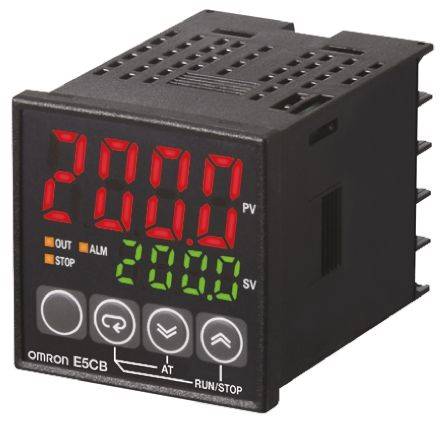
Omron E5CB PID Temperature Controller, 48 x 48mm, 1 Output: 1x Relay, 1x Logic, 100 ? 240 V ac Supply Voltage
$1.00 Add to cart -

Omron E5CC PID Temperature Controller, 48 x 48mm, 1 Output Relay, 100 ? 240 V ac Supply Voltage
$1.00 Add to cart -
3 TONES ELECTRONIC BUZZER
$1.00 Add to cart


Reviews
There are no reviews yet.